Shunt pictures
- FORDification
- Site & Forum Admin
- Posts: 8050
- Joined: Sun Jul 11, 2004 12:52 am
- Location: Kansas, Wellsville
- Contact:
Shunt pictures
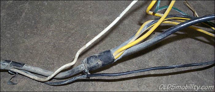
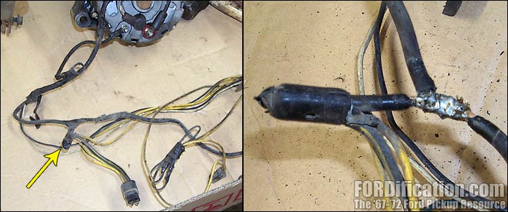
The following picture of the shunt necessary to run the ammeter on a full instrumentation instrument cluster was on a '67 F250 Camper Special. In the left pic you can see that it was just wrapped by the factory and almost looks amateur-ish. The pic on the right shows what it looks like after removing the factory wrapping :
I was planning on following all the wires coming from the shunt and taking notes, but ran out of time before having to head home. I plan on continuing this research in the very near future. So anyway... it appears that on early models the ammeter circuit was 'spliced' in, but the installation was refined for the later models. This picture of the shunt was taken of a later F100 harness, I believe it was from a '71:
____| \__
-O-----O- Keith
'67 F-100 2WD SWB ~ '69 F-100 4WD SWB w/7" chop ~ 1975 F-250 Ranger XLT Supercab Camper Special
My '67 restoration video
-> Posting and you! <-a MUST watch for all!!
-O-----O- Keith
'67 F-100 2WD SWB ~ '69 F-100 4WD SWB w/7" chop ~ 1975 F-250 Ranger XLT Supercab Camper Special
My '67 restoration video
-> Posting and you! <-a MUST watch for all!!
-
- New Member
- Posts: 9
- Joined: Wed Dec 08, 2004 4:49 pm
- Location: Kentucky
- Contact:
re: Shunt pictures
Keith,
I am needing a little info about the shunt. I really appreciate you posting these pics.. they will be helpful when I am trying to locate one of these in the junkyard.
A couple questions I have are... is the shunt required for just the F600 panel or is it also required for all full instrument gauges. My truck came with idiot lights. So from the way I understand it.. I have to have a shunt to make the full instrumentation gauges work no matter if thier F600 or the stock ones correct?
I seen in the pictures that you posted of the shunt, that it looks like it is located between the alternator and the battery? Since you have one and can look at it for me, how easy would it be to get off of a truck in a junkyard. What is required to remove the shunt and to reinstall it in my truck. Is it as easy as splicing it in on my truck after removing it from the donor truck? I think these questions would help alot of people on the board if anyone has done this modification before, because the f-600 gauges are very popular.
Any Info would be greatly appreciated,
Thanks,
Steve
1968 Ford f100
- FORDification
- Site & Forum Admin
- Posts: 8050
- Joined: Sun Jul 11, 2004 12:52 am
- Location: Kansas, Wellsville
- Contact:
re: Shunt pictures
Talk about timing! I've been working this evening on a tutorial to post to the site, explaining the wiring setup. Unfortunately, I don't have all the info I need to complete this yet, but I'm (tentatively) planning on being in the shop all day on Sunday, and hope to finish tracing wires and drawing up a schematic to help.
The harness with the shunt that I'll be using for the tutorial is the one from the '67 F250 CS. On this harness, the shunt is wired into the cable which extends from the starter solenoid to the alternator. There are three wires extending out from the shunt...two yellow wires and a larger black wire with a yellow stripe. One yellow wire goes to the 'S' (?) terminal on the voltage regulator. The other two wires go up into a square 4-terminal connector by the firewall which in turn goes into the cab and under the dash...but that's as far as I've traced it so far.
From what I've been learning so far, it's not going to be a simple job of just splicing a junkyard shunt in, since other areas of the harness are different as well. Obviously, the standard-instrumentation engine harness is set up a little different for the voltage regulator, plus from what I understand the plug connector at the instrument panel is also set up a little differently. However, I've got versions of the standard instrumentation and full instrumentation wiring harnesses in the shop, and I'll be comparing them and following all the wires to ascertain exactly where they go and how they differ.
...and yes, the F600 panel also uses the same basic style of ammeter, so if you wanted to use the factory gauges in the panel, the shunt would be necessary for it as well.
Stay tuned...I hope to have some more info for you by the end of the weekend.
____| \__
-O-----O- Keith
'67 F-100 2WD SWB ~ '69 F-100 4WD SWB w/7" chop ~ 1975 F-250 Ranger XLT Supercab Camper Special
My '67 restoration video
-> Posting and you! <-a MUST watch for all!!
-O-----O- Keith
'67 F-100 2WD SWB ~ '69 F-100 4WD SWB w/7" chop ~ 1975 F-250 Ranger XLT Supercab Camper Special
My '67 restoration video
-> Posting and you! <-a MUST watch for all!!
- bluef250
- Blue Oval Fanatic
- Posts: 924
- Joined: Fri Oct 29, 2004 8:49 pm
- Location: Arizona
re: Shunt pictures
The shunt actually is the wire between the splice and the starter solenoid. The splice in the picture looks like an amateur put it together. The wiring diagram shows the same circuit configuration for the amp meter on the f 100 to f 350 gauge as on the heavier truck gauge. Therefore, if the 4 amp fuses are kept in place (at the solenoid and at the splice) the amp gauge on the heavier truck gauge should work just like the light truck gauge. If the heavy truck gauge is more sensitive to the current than the light truck gauge, the heavy truck gauge may respond more, have more movement. The larger the current generated by the alternator the more you need the 4 amp fuses. If you use a larger alternator, then the wire between the alternator and the starter solenoid should to be increased in diameter - heavier gauge to carry more current. The five wires at the splice go to the 1) alternator, to the 2) voltage regulator, the 3) switch, the 4) amp gauge, and to the 5) starter solenoid. My guess is that each wire gauge was selected to balance the charging circuit. The smaller the wire gauge the higher the resistance, the less current it will pass at a given voltage.
- FORDification
- Site & Forum Admin
- Posts: 8050
- Joined: Sun Jul 11, 2004 12:52 am
- Location: Kansas, Wellsville
- Contact:
Re: re: Shunt pictures
Oh really?? Hmmm....OK, this is new information I have to digest. I had to whip up another photo with the wires labeled and attach it to this post, so I can try to understand what you're saying. Refer to it for the following questions.bluef250 wrote:The shunt actually is the wire between the splice and the starter solenoid....
1) In the diagram, what I have marked as "C" isn't the shunt, you're saying is just basically a large junction? I guess I was looking at this as "A" and "B" being the same single cable, with "C" being spliced into it in the middle. But if I'm understanding you correctly, you're saying that "A" goes into the junction "C" and that "B" is spliced into "A"?
2) The cable that I have marked "A" is the one which goes from the starter solenoid to the alternator. You're saying that the cable "A" is ITSELF the shunt?
3) So then cable "B" is the one which would go straight to the solenoid for trucks without an ammeter and there would be no cable "A"?
4) Neither of the '67 full-instrumentation harnesses I've inspected had fuses. Where exactly would they go? How would this affect the resistance of the shunt?
I know the splice looks home-made, but it's not. I unwrapped it myself, and the wrapping was all one piece with the rest of the harness...so it definitely came that way from the factory, unless a previous owner rewrapped the entire harness....and since this wiring came from a truck with only 27K original miles, I'm leaning more towards this being a factory setup....but I've been wrong before.
I appreciate your input in this....it's nice being able to pick a knowledgable brain! Thanks!
You do not have the required permissions to view the files attached to this post.
____| \__
-O-----O- Keith
'67 F-100 2WD SWB ~ '69 F-100 4WD SWB w/7" chop ~ 1975 F-250 Ranger XLT Supercab Camper Special
My '67 restoration video
-> Posting and you! <-a MUST watch for all!!
-O-----O- Keith
'67 F-100 2WD SWB ~ '69 F-100 4WD SWB w/7" chop ~ 1975 F-250 Ranger XLT Supercab Camper Special
My '67 restoration video
-> Posting and you! <-a MUST watch for all!!
- bluef250
- Blue Oval Fanatic
- Posts: 924
- Joined: Fri Oct 29, 2004 8:49 pm
- Location: Arizona
re: Shunt pictures
The way the circuits work is an application of Ohm's Law. I will try to do some more on this today. On your harness, what gauge wire goes between the alternator and the starter relay? Between the splice and the starter relay? The fuses on my '68 are immediately after the starter relay and after the splice on the wire to the amp gauge. Also any fuses, splices, connections, gauges, etc. will change the resistance, maybe less maybe more than the wire along. The difference in gauge will create a difference in the resistance. Resistances in series are added. For resistances in parallel the inverses are added to determine the inverse of the total resistance. As a wire carries more current it will heat up and the resistance increases. That's why when you have a short to ground often you will burn up the insulation on the wire. Using some approximations, I got a current ratio of about 1 and between 20 to 40 for the two wires. For a dynamic system, this probably would be okay.
- 68F250
- Blue Oval Guru
- Posts: 1174
- Joined: Thu Jul 22, 2004 3:26 pm
- Location: California, Brea
re: Shunt pictures
That's my understanding of the Ford shunts, they are just smaller sized wire designed to drop voltage. The voltage drop across the shunt is measured by the ammeter (really a sensitive voltmeter).
Wish I was there to help you tear apart that harness. Those two inline fuses are the two wires that go to the ammeter. Both sides need to be fused because both sides are hot, only one's just a little hotter than the other. The difference in 'hotness' changes polarity, meaning your charging or discharging. Interesting that the '67 doesn't have any fuses, the '68 and later ones do. These fuses can cause problems down the road though, the connections develop resistance and knock down the signal level to the gauge. Same deal for the connections on the back of the gauge, a little resistance will knock down the signal to nothing.
- bluef250
- Blue Oval Fanatic
- Posts: 924
- Joined: Fri Oct 29, 2004 8:49 pm
- Location: Arizona
re: Shunt pictures
The definition of an Electrical Shunt - n : a conductor having low resistance in parallel with another device to divert a fraction of the current [syn: shunt, bypass]
The analogy of water pipes was used. Two parallel pipes connected together at end nodes will have the same pressure drop (voltage), but different currents (flow). The large one would have more capacity than the smaller.
The thought had crossed my mind also that all the "devices" put in the gauge circuit would "wear" causing problems. The resistance developed by these "devices" would then make the gauge less senitive. Although in a review of a number of sites today, Ford created a problem with this design. I found this
"AutomotiveMileposts.com
Vol. 2, No. 7
January 5, 2004
Automotive Mileposts Troubleshooting/Tech Tips Series
..... (talking about the early style amp gauges that took all current) In a worst case scenario, the potential for an electrical fire was very much a possibility. Around 1966 or 1967, Ford redesigned this circuit and installed an Ammeter Gauge in many of its cars that used gauges instead of warning lights to notify the driver about charging system health. A shunt wire in the circuit allowed only a small amount of electrical power to flow through the gauge itself, which meant the needle didn't move very much. Only very strong charging or discharging would cause the needle to move, and even then the movement was so slight most people didn't notice it.
This resulted is customers and service technicians questioning how to tell if the gauge was operating correctly. Ford released a Technical Service Bulletin (TSB) to advise service personnel on the proper procedure for testing the gauge.
Here is the abbreviated official procedure outlined in the TSB:
* Close all doors and turn off all electrical accessories
* Turn ignition switch to "Accessory" position
* While closely observing Ammeter Gauge, turn on headlamps
* Any deflection of the needle towards "D" (discharge) means the gauge is fine
Normally, pressing on the brake pedal to activate the brake lights or opening a door to turn on the interior courtesy lights should also cause the needle to deflect, but it's rare to find one today that actually does anything."
So it seems like this has been a problem from the get go. Also, this caught my attention:
"AMP gauges at the dash are troublesome.
They should be by-passed, and then install a VOLT gauge.
by Mark Hamilton.
GM also up-graded their system long before the Dodge Boys. When GM introduced the alternator with ’63 models, it was controlled by a more complicated but more efficient voltage regulator system. And the new GM system could support a warning light at the dash. The warning light was often standard equipment and the gauge was an option. GM vehicles built with the gauge option also had a more modern design of AMP gauge at the dash. The newer AMP gauge was a remote shunt type design–a length of the battery charging wire in the under-hood harness served as the shunt. The dash gauge and related wiring no longer handled heavy current load. Same with Ford in ’65 and newer model cars–the Ford system could work with a warning light at the dash, and cars that came dash gauges had a remote shunt type amp gauge." It seems that maybe Ford "borrowed" the design.
Another observation is that the splice is away from the alternator, Why? Why not use the alternator post for a termination point? It may be that Ford matched specific lengths of wire between the splice and solenoid to get an acceptable current ratio.
- 68F250
- Blue Oval Guru
- Posts: 1174
- Joined: Thu Jul 22, 2004 3:26 pm
- Location: California, Brea
re: Shunt pictures
bluef250, thanks for digging up that info. I have that TSB that talks about the lazy gauge and how to test it, thought it was pretty lame when they said any deflection is fine. Maybe we should send Keith a scan of that for fun.
Ya know, my personal experience is these trucks have the worst responding ammeter. The ones in the vans seem to work a lot better but have the same problem with connector resistance in the fuses and gauge posts. Maybe the trucks got the shunt gauge a little too heavy? I remember someone at the other site pulled some strands out of his shunt to get more response. It worked but he was such a smarta$$ about it that I didn't pay much attention. Seems if you pull out too many you can't go back.
- bluef250
- Blue Oval Fanatic
- Posts: 924
- Joined: Fri Oct 29, 2004 8:49 pm
- Location: Arizona
re: Shunt pictures
68F250 - why not scan TSB and let Keith put it on the site? Going back to the pipe analogy if you want more flow in the smaller pipe, you increase its size or decrease the size of the larger. Forget about decreasing the larger pipe (pulling out wire strands). Why not install a larger gauge wire from the fuse to the gauge? Increasing by one wire size (say from 14 awg to 12 awg) increases the amperage by about 60%, increase by two wire sizes (say from 14 awg to 10 awg) increases the amperage by about 150%. At the same time, you could eliminate all the connections between the gauge and the fuse. The gauge is still protected by the fuses.
- FORDification
- Site & Forum Admin
- Posts: 8050
- Joined: Sun Jul 11, 2004 12:52 am
- Location: Kansas, Wellsville
- Contact:
Re: re: Shunt pictures
After reading your post, I got to wondering the same thing myself. From the way it's set up here, the alternator would also be getting the reduced voltage from the shunt. It would seem to me that the splice should be AFTER the alternator connection. Actually, what would seem to make more sense to me (with my limited grasp of the subject) is that both the alternator cable AND the shunt wire to the ammeter should be separate cables coming from the starter solenoid....parallel cables, but not connected except at the solenoid.bluef250 wrote:....Another observation is that the splice is away from the alternator, Why? Why not use the alternator post for a termination point? It may be that Ford matched specific lengths of wire between the splice and solenoid to get an acceptable current ratio.
I can definitely see now why I should have paid more attention in school! Thanks for your input guys. I'd REALLY like to get this figured out and put down into a technical paper, so that future truck owners can get a grasp of how this works. I'd be happy to post the TSB on the site if it could be forwarded to me.
____| \__
-O-----O- Keith
'67 F-100 2WD SWB ~ '69 F-100 4WD SWB w/7" chop ~ 1975 F-250 Ranger XLT Supercab Camper Special
My '67 restoration video
-> Posting and you! <-a MUST watch for all!!
-O-----O- Keith
'67 F-100 2WD SWB ~ '69 F-100 4WD SWB w/7" chop ~ 1975 F-250 Ranger XLT Supercab Camper Special
My '67 restoration video
-> Posting and you! <-a MUST watch for all!!
- bluef250
- Blue Oval Fanatic
- Posts: 924
- Joined: Fri Oct 29, 2004 8:49 pm
- Location: Arizona
re: Shunt pictures
Keith, As you are doing the research, could you measure the length of each segment of wire and determine the gauge? Will email a copy of the notes I gathered today. You may be able to use them for the tech article. Thanks Phil
- FORDification
- Site & Forum Admin
- Posts: 8050
- Joined: Sun Jul 11, 2004 12:52 am
- Location: Kansas, Wellsville
- Contact:
re: Shunt pictures
I will definitely do that this Sunday when I'm at the shop. Thanks, Phil!
____| \__
-O-----O- Keith
'67 F-100 2WD SWB ~ '69 F-100 4WD SWB w/7" chop ~ 1975 F-250 Ranger XLT Supercab Camper Special
My '67 restoration video
-> Posting and you! <-a MUST watch for all!!
-O-----O- Keith
'67 F-100 2WD SWB ~ '69 F-100 4WD SWB w/7" chop ~ 1975 F-250 Ranger XLT Supercab Camper Special
My '67 restoration video
-> Posting and you! <-a MUST watch for all!!
- FORDification
- Site & Forum Admin
- Posts: 8050
- Joined: Sun Jul 11, 2004 12:52 am
- Location: Kansas, Wellsville
- Contact:
re: Shunt pictures
OK, the results are in....and quite frankly, I'm a little surprised. No, I take that back...I'm VERY surprised! Granted, I don't know much at all about automotive wiring, but apparently some of what I thought I knew was incorrect. (Imagine that!)
I've been thinking of a 'shunt' as a thing or object, and not as a connection method, even after bluef250's definition of the term in his post above. However, after having my father-in-law spend some time with me at the shop today explaining things to me and helping me trace wires and take readings, I'm getting a much better understanding of how the system is put together, and some of what you guys were stating above is starting to make sense. I still have a ways to go, but I'm making progress.
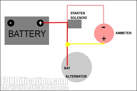
Here's a diagram I just whipped up showing the factory ammeter connection:
The most surprising thing I found out was that there are NO resistance wires...not in the solenoid-to-alternator cable nor the ammeter leads. The 10 AWG cable from the solenoid to the alternator is one piece and has virtually NO resistance, using a sensitive ohmmeter for testing. However, since further details of today's investigation would probably be too lengthy for the thread, I've also whipped up a webpage detailing what I found and really want you all to take a look and offer comments, suggestions or rebuttals:
Factory Ammeter Wiring
Last edited by FORDification on Mon Mar 14, 2005 8:51 am, edited 1 time in total.
____| \__
-O-----O- Keith
'67 F-100 2WD SWB ~ '69 F-100 4WD SWB w/7" chop ~ 1975 F-250 Ranger XLT Supercab Camper Special
My '67 restoration video
-> Posting and you! <-a MUST watch for all!!
-O-----O- Keith
'67 F-100 2WD SWB ~ '69 F-100 4WD SWB w/7" chop ~ 1975 F-250 Ranger XLT Supercab Camper Special
My '67 restoration video
-> Posting and you! <-a MUST watch for all!!
- 68F250
- Blue Oval Guru
- Posts: 1174
- Joined: Thu Jul 22, 2004 3:26 pm
- Location: California, Brea
re: Shunt pictures
Hmm, that is strange. The field is going to the starter solenoid? It should be going to the voltage regulator. The ammeter is measuring field current? Gotta think about that.
Thanks for spending the time going thru the harness, I've been playing plumber all weekend.