How the Distributor / Coil wires work
Moderators: FORDification, Thunderfoot
- Thunderfoot
- 100% FORDified!
- Posts: 2207
- Joined: Tue Apr 17, 2007 2:34 pm
- Location: Idaho, Boise
How the Distributor / Coil wires work
Updated on 1-19-08
Ok, I spent some time today making up these drawings with some explanation on how the wires go from the ignition switch to the coil to the distributor. This is to help explain how it all works a little better…
Let me know if this info is good – bad-- to complicated -- not really useful -- etc…
When you go to check if your wire from the ignition switch to the coil is resistive or not buy using a voltage meter. You are looking for 6-9 Volts on the positive connection on the coil but if the points are open it will not give you the correct reading it will give you 12V. If the points are closed then you will get the correct reading or you can do what I have a shown below to be sure that the circuit is complete…
If this works out good for everyone I will continue to add information to this for the ignition circuits on our trucks…
Click on the image to open it and then be sure to expand it to full size.
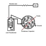
This shows the parts of the ignition circuit.
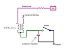
This is the same thing just a little simpler so hopefully easier to understand.
The coil is the same thing as a Transformer it steps up the voltage that goes out to the spark plugs. (on a side note; a transformer wont work unless the voltage is being turned off and on for DC or have AC hooked to it. It's the way it works... that is what the points are doing by opening and closing the circuit to ground.)
The Condenser is the same thing as a Capacitor (Cap) it is use here to help take the arcing out of the points when they open and close.
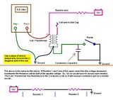
Updated on 1-19-08
This shows how to go about measuring the coil wire to see if it is a resistive wire or not and also gives some explanation on how a DC series circuit works.
You will see that I say to hook up a temporary wire to the Negative terminal on the coil (this is the same wire that is going to the points) and connect it to ground. This makes the circuit complete just as if the points were closed so you don't have to worry about if they are open or closed.
Or you can remove the distributor cap and turn the motor over until the points are closed, but the other way you know for sure that the circuit is complete.
Note: you never want to leave the key on in the RUN position for an extend amount of time with the points closed or with this temporary wire added, as the ignition wire (resistive wire) will get warm and over a time could burn up. It would take a while but it could happen and is something to always remember… same thing with listening to the radio with the motor off with the key in the RUN position instead of the ACC position, if the points happen to be closed or if they are almost closed you can get some arcing and wear out your points quickly too.
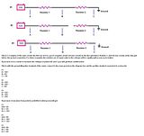
This shows a little more about how reading the voltage across resistors in a DC series circuit works. Also, note that lots of things act like a resistor… light bulbs are one that no one thinks of but anything that is using power has some resistance value to it in one way or another…
Anyway, let me know what you think. I take all criticism good or bad… and if you see something that you think is wrong let me know and I will research it more as it has been 8 years after getting my electronics degree and I don’t get to use it that much in the job I have now, so I have to knock some of the cobwebs out once in a while.
Last edited by Thunderfoot on Sat Jan 19, 2008 12:57 pm, edited 5 times in total.
Shayne
I'm not "Brand Loyal" Ford-Chevy-Dodge-Toyota I have them all, one even cross mixed...
If it Looks good and Works good then it's ok by me. Everything has its issues from time to time...
69 SWB (project) & 69 Highboy (driver/project)
http://s197.photobucket.com/albums/aa29 ... d%20truck/
http://www.fordification.com/galleries/ ... ?cat=10399
-
- Blue Oval Guru
- Posts: 1341
- Joined: Sun Aug 06, 2006 5:41 pm
- Location: Utah, Springville
- Contact:
- basketcase0302
- 100% FORDified!
- Posts: 6805
- Joined: Thu Jan 26, 2006 7:11 am
- Location: Hawthorne, Florida
re: How the Distributor / Coil wires work
Thunderfoot,
Looks good man.
Remember first getting into A/C at about 16.
Schematics were like a foreign language to me back then.
For me it was nothing some expierence didn't fix but...
Simple is nice!
Jeff
Looks good man.
Remember first getting into A/C at about 16.
Schematics were like a foreign language to me back then.
For me it was nothing some expierence didn't fix but...
Simple is nice!
Jeff
Jeff
http://www.fordification.com/forum/view ... 22&t=46251
SOLD-71 F-350 dually flatbed, 302 / .030 over V-8 with a "baby"C-6, B & M truckshifter, Dana70/4.11 ratio, intermittent wipers, tilt steering, full LED lighting on the flat bed, and no stereo yet (this way I can hear the rattles to diagnose)! SOLD!
Many Ford bumps / one 76' EB / and several dents through the years.
A lot of "oddball" Ford parts collected from working on them for 34 years now!
2008 Ford Escape 4 x 4
- Thunderfoot
- 100% FORDified!
- Posts: 2207
- Joined: Tue Apr 17, 2007 2:34 pm
- Location: Idaho, Boise
That sounds good, there will always be some difference in what one meter will read compared to another and as the points are opening and closing it will affect how it looks to the meter.craftsman wrote:It is helpful,Thanks
question- on my truck when running the voltage at the coil was 10 volts, does this sound right?
Shayne
I'm not "Brand Loyal" Ford-Chevy-Dodge-Toyota I have them all, one even cross mixed...
If it Looks good and Works good then it's ok by me. Everything has its issues from time to time...
69 SWB (project) & 69 Highboy (driver/project)
http://s197.photobucket.com/albums/aa29 ... d%20truck/
http://www.fordification.com/galleries/ ... ?cat=10399
I'm not "Brand Loyal" Ford-Chevy-Dodge-Toyota I have them all, one even cross mixed...
If it Looks good and Works good then it's ok by me. Everything has its issues from time to time...
69 SWB (project) & 69 Highboy (driver/project)
http://s197.photobucket.com/albums/aa29 ... d%20truck/
http://www.fordification.com/galleries/ ... ?cat=10399
-
- New Member
- Posts: 67
- Joined: Thu Jan 03, 2008 9:15 pm
- Location: Bloomington, Indiana
Hey man, the voltages in the last diagram are a little weird. I am scamming some company time to look at this, so I can't write as helpfull a reply as I would like, but with the first two circuits, the reading at point C should be 0. This is because the voltmeter is essentially connected between ground and ground...
Thanks for the post, it has been a fun brain teaser and has helped me dust out some of my own cobwebs.
- Thunderfoot
- 100% FORDified!
- Posts: 2207
- Joined: Tue Apr 17, 2007 2:34 pm
- Location: Idaho, Boise
Hey, thanks for catching that!Alfred Lord Tenniscourt wrote:Hey man, the voltages in the last diagram are a little weird. I am scamming some company time to look at this, so I can't write as helpfull a reply as I would like, but with the first two circuits, the reading at point C should be 0. This is because the voltmeter is essentially connected between ground and ground...
Thanks for the post, it has been a fun brain teaser and has helped me dust out some of my own cobwebs.
Yes, in the #1 circuit (first example) point C would be 0V as both leads of the meter are basically on the same point so no difference in potential.
I had the #2 one right but missed that on the #1.
I made the change and re-uploaded the drawing.
Thanks again for seeing that!
Shayne
I'm not "Brand Loyal" Ford-Chevy-Dodge-Toyota I have them all, one even cross mixed...
If it Looks good and Works good then it's ok by me. Everything has its issues from time to time...
69 SWB (project) & 69 Highboy (driver/project)
http://s197.photobucket.com/albums/aa29 ... d%20truck/
http://www.fordification.com/galleries/ ... ?cat=10399
I'm not "Brand Loyal" Ford-Chevy-Dodge-Toyota I have them all, one even cross mixed...
If it Looks good and Works good then it's ok by me. Everything has its issues from time to time...
69 SWB (project) & 69 Highboy (driver/project)
http://s197.photobucket.com/albums/aa29 ... d%20truck/
http://www.fordification.com/galleries/ ... ?cat=10399
- AlleyCat
- Blue Oval Guru
- Posts: 1283
- Joined: Sat May 12, 2007 8:28 pm
- Location: Pennsylvania, Pittsburgh
re: How the Distributor / Coil wires work
Shayne, take a look at the voltage reading in the 3rd drawing.Now look at the switch ( points).Meter should read 12 volts with the points open.
Good start on a tutorial.
Clay
72 F100 4x2 Custom,289, C4 " Slow Ride "
70 F250 4x2 Ranger XLT , 360, C6 "B52 - IV"
96 F150 4x2 XL, 300, E4OD, daily driver
" Professional Wrecker Operators - We Pull for America "
72 F100 4x2 Custom,289, C4 " Slow Ride "
70 F250 4x2 Ranger XLT , 360, C6 "B52 - IV"
96 F150 4x2 XL, 300, E4OD, daily driver
" Professional Wrecker Operators - We Pull for America "
- Thunderfoot
- 100% FORDified!
- Posts: 2207
- Joined: Tue Apr 17, 2007 2:34 pm
- Location: Idaho, Boise
Re: re: How the Distributor / Coil wires work
Clay, Are you talking about the picture that has the meter on it and shows the points are open? Check out the extra wire I said to add temporarily to the (-) side of the coil to ground. This makes the points open or closed a moot point.AlleyCat wrote:Shayne, take a look at the voltage reading in the 3rd drawing.Now look at the switch ( points).Meter should read 12 volts with the points open.
Good start on a tutorial.
I state this to the left of the negative connection of the meter to ground I will make that stand out more and explain that better in the tutorial.
So far looks like the response has been good so I will keep working on improving and expanding it out with troubleshooting tips and more theory explanations.
Thanks for all the replies so far! If anyone has suggestions on how it would look better let me know.
Shayne
I'm not "Brand Loyal" Ford-Chevy-Dodge-Toyota I have them all, one even cross mixed...
If it Looks good and Works good then it's ok by me. Everything has its issues from time to time...
69 SWB (project) & 69 Highboy (driver/project)
http://s197.photobucket.com/albums/aa29 ... d%20truck/
http://www.fordification.com/galleries/ ... ?cat=10399
I'm not "Brand Loyal" Ford-Chevy-Dodge-Toyota I have them all, one even cross mixed...
If it Looks good and Works good then it's ok by me. Everything has its issues from time to time...
69 SWB (project) & 69 Highboy (driver/project)
http://s197.photobucket.com/albums/aa29 ... d%20truck/
http://www.fordification.com/galleries/ ... ?cat=10399
- AlleyCat
- Blue Oval Guru
- Posts: 1283
- Joined: Sat May 12, 2007 8:28 pm
- Location: Pennsylvania, Pittsburgh
Re: re: How the Distributor / Coil wires work
Oops, I need b***h slapped for that one.Thunderfoot wrote:AlleyCat wrote:
Clay, Are you talking about the picture that has the meter on it and shows the points are open? Check out the extra wire I said to add temporarily to the (-) side of the coil to ground. This makes the points open or closed a moot point.
I state this to the left of the negative connection of the meter to ground I will make that stand out more and explain that better in the tutorial.
Clay
72 F100 4x2 Custom,289, C4 " Slow Ride "
70 F250 4x2 Ranger XLT , 360, C6 "B52 - IV"
96 F150 4x2 XL, 300, E4OD, daily driver
" Professional Wrecker Operators - We Pull for America "
72 F100 4x2 Custom,289, C4 " Slow Ride "
70 F250 4x2 Ranger XLT , 360, C6 "B52 - IV"
96 F150 4x2 XL, 300, E4OD, daily driver
" Professional Wrecker Operators - We Pull for America "
- Thunderfoot
- 100% FORDified!
- Posts: 2207
- Joined: Tue Apr 17, 2007 2:34 pm
- Location: Idaho, Boise
re: How the Distributor / Coil wires work
Not really, you made a good point that I didn't explain it there very well so it was good info for me to make it better
Thanks
Thanks
Shayne
I'm not "Brand Loyal" Ford-Chevy-Dodge-Toyota I have them all, one even cross mixed...
If it Looks good and Works good then it's ok by me. Everything has its issues from time to time...
69 SWB (project) & 69 Highboy (driver/project)
http://s197.photobucket.com/albums/aa29 ... d%20truck/
http://www.fordification.com/galleries/ ... ?cat=10399
I'm not "Brand Loyal" Ford-Chevy-Dodge-Toyota I have them all, one even cross mixed...
If it Looks good and Works good then it's ok by me. Everything has its issues from time to time...
69 SWB (project) & 69 Highboy (driver/project)
http://s197.photobucket.com/albums/aa29 ... d%20truck/
http://www.fordification.com/galleries/ ... ?cat=10399
- seattle67
- Blue Oval Fan
- Posts: 739
- Joined: Sun Aug 12, 2007 12:48 am
- Location: Washington, Seattle
re: How the Distributor / Coil wires work
Those are great Thunderfoot, real handy!
Dan
"I plan to start procastinating immediately"