Driveshaft angles
Moderators: FORDification, 70_F100
-
orre_s86
- New Member

- Posts: 4
- Joined: Thu Apr 07, 2016 11:04 am
Driveshaft angles
Hallo,
I just lowered my 68 - f100 with the djm lowering kit. I am getting a bit confused about setting up the driveline angles on a multiple shaft installation, and would be very thankful if i could get som input. The angles are set up as in the picture right now, would this work or what angle/angles should i change?
Thanks in advance/ Oskar
You do not have the required permissions to view the files attached to this post.
- eggman918
- Blue Oval Guru

- Posts: 1098
- Joined: Fri Nov 20, 2009 12:56 pm
- Location: Paulden,AZ.
Re: Driveshaft angles
This won't give you chassis specific numbers but it will give you the generic angles Dana/Spicer use.
http://www2.dana.com/pdf/DSIG-3311.pdf
http://www2.dana.com/pdf/DSIG-3311.pdf
Steve
The"Filthy Beast"- '68 F-250 Crew Cab 131"W/B 4x4 4BT compounds hx30/Wh1c,5x.012" sac injectors/ZF 5/NP203-205 /3.54 44 trutrack front/60 trutrack rear on 33's. 2nd owner
"Beauty is only skin deep....Ugly is to the bone"
It is more important to understand what you don't know than what you do know,because then you can start to learn..???
"you must deal with the attaboys and the ass chewing s with your head up and looking them in the eyes" T.J.E. aka My Dad
There are only three types of people wolves, sheepdogs, and sheep. What are you?
- Ranchero50
- Moderator

- Posts: 5799
- Joined: Wed Nov 08, 2006 7:02 pm
- Location: Maryland, Hagerstown
- Contact:
Re: Driveshaft angles
Ideally the pinion shaft angle should be 1-2` below the angle of the trans shaft centerline to allow for torque rotation on the axle housing and the carrier bearing should have no angles on it. Per your picture, the 5` on the pinion should be 2` and the carrier bearing should be raised so the drive shafts have the same angle.
The more joints and changes of direction, the more vibrations you'll induce into the driveline.
You want the minimum angle between shafts as that is what induces vibration. At 5k shaft speed they want a total of less that 3.2` of angle between any point.
The more joints and changes of direction, the more vibrations you'll induce into the driveline.
You want the minimum angle between shafts as that is what induces vibration. At 5k shaft speed they want a total of less that 3.2` of angle between any point.
'70 F-350 CS Cummins 6BT 10klb truck 64k mile Bahama Blue
Contact me for CNC Dome Lamp Bezels and Ash Tray pulls.
Contact me for CNC Dome Lamp Bezels and Ash Tray pulls.
-
orre_s86
- New Member

- Posts: 4
- Joined: Thu Apr 07, 2016 11:04 am
Re: Driveshaft angles
Thank you very mutch for your input!
So what you are saying is changing it like the last one of these shown in the picture? Gearbox and first shaft in the same (3 deg) angle, pinion angle at 2 deg and let the second shaft have whatever angle it gets?
Thank you/ Oskar
So what you are saying is changing it like the last one of these shown in the picture? Gearbox and first shaft in the same (3 deg) angle, pinion angle at 2 deg and let the second shaft have whatever angle it gets?
Thank you/ Oskar
You do not have the required permissions to view the files attached to this post.
- eggman918
- Blue Oval Guru

- Posts: 1098
- Joined: Fri Nov 20, 2009 12:56 pm
- Location: Paulden,AZ.
Re: Driveshaft angles
You need a minimum operating angle .5' on a U-joint so the 3 and 3 is a no go
Steve
The"Filthy Beast"- '68 F-250 Crew Cab 131"W/B 4x4 4BT compounds hx30/Wh1c,5x.012" sac injectors/ZF 5/NP203-205 /3.54 44 trutrack front/60 trutrack rear on 33's. 2nd owner
"Beauty is only skin deep....Ugly is to the bone"
It is more important to understand what you don't know than what you do know,because then you can start to learn..???
"you must deal with the attaboys and the ass chewing s with your head up and looking them in the eyes" T.J.E. aka My Dad
There are only three types of people wolves, sheepdogs, and sheep. What are you?
The"Filthy Beast"- '68 F-250 Crew Cab 131"W/B 4x4 4BT compounds hx30/Wh1c,5x.012" sac injectors/ZF 5/NP203-205 /3.54 44 trutrack front/60 trutrack rear on 33's. 2nd owner
"Beauty is only skin deep....Ugly is to the bone"
It is more important to understand what you don't know than what you do know,because then you can start to learn..???
"you must deal with the attaboys and the ass chewing s with your head up and looking them in the eyes" T.J.E. aka My Dad
There are only three types of people wolves, sheepdogs, and sheep. What are you?
- two-bit
- Blue Oval Fan

- Posts: 620
- Joined: Thu Jul 06, 2006 6:19 pm
- Location: Michigan, Ishpeming
Re: Driveshaft angles
In our shop we have built a couple of long frame semi tractors into quad axle dumps.
When i set up the drive shaft i run the first shaft at a 3* down angle from the from the trans to the carrier bearing.
The second shaft from the carrier to the front pinion i let it be what it will.
We don't change our pinion angles on the diffs. Just move the axles back, and build the driveshafts accordingly.
I Never go more than 3* on the front shaft.
Have seen a few that were set up at more than 3* and it tore up the u-joints something fierce very quickly.
I would set up your drive shaft like the third diagram with these changes.
Set your front shaft at a 3* down from the gear box output. Let the second shaft be what it is. Pinion angle of 2* ? Not sure about that.
I know those angles will work for a quad axle KW chassis. So i am fairly sure they would work for you.
Its my opinion, for what its worth.
Two-bit
Living life full throttle on the North Coast of America!!!
72' F-350, DRW, 360, NP435, Dana 70, 159" WB, P.S., P.B., 12' flatbed, 10,000 GVW.
72' F-350, DRW, 360, NP435, Dana 70, 159" WB, P.S., P.B., 12' flatbed, 10,000 GVW.
-
orre_s86
- New Member

- Posts: 4
- Joined: Thu Apr 07, 2016 11:04 am
Re: Driveshaft angles
As i understand it from the spicer pdf, you can have them in level if you rotate the yoke.
Is this wrong?
Thank you\ Oskar
Is this wrong?
Thank you\ Oskar
- Ranchero50
- Moderator

- Posts: 5799
- Joined: Wed Nov 08, 2006 7:02 pm
- Location: Maryland, Hagerstown
- Contact:
Re: Driveshaft angles
I think what you will see is that you can do anything you like as long as the U joint is happy. I like to minimize the deflection at the U joints. No deflection, no motion and no wear. The more deflection, the more the roller's roll and the more they will wear. Excessive deflection will exacerbate the wear and they will fail quickly.orre_s86 wrote:As i understand it from the spicer pdf, you can have them in level if you rotate the yoke.
Is this wrong?
Thank you\ Oskar
'70 F-350 CS Cummins 6BT 10klb truck 64k mile Bahama Blue
Contact me for CNC Dome Lamp Bezels and Ash Tray pulls.
Contact me for CNC Dome Lamp Bezels and Ash Tray pulls.
-
orre_s86
- New Member

- Posts: 4
- Joined: Thu Apr 07, 2016 11:04 am
Re: Driveshaft angles
Im new to driveline tech, so im happy as long as everything works and holds togheter 
So what you are saying is that not having a angle wont cause any problems for me? Dosent even have to rotate the yoke to have it working?
Outherwise, would it be wrong to drive it like this?
Thank you/ Oskar
So what you are saying is that not having a angle wont cause any problems for me? Dosent even have to rotate the yoke to have it working?
Outherwise, would it be wrong to drive it like this?
Thank you/ Oskar
You do not have the required permissions to view the files attached to this post.
- Ranchero50
- Moderator

- Posts: 5799
- Joined: Wed Nov 08, 2006 7:02 pm
- Location: Maryland, Hagerstown
- Contact:
Re: Driveshaft angles
This is how mine looks. Maybe a degree or two between joints at the carrier bearing and as straight as I can get it otherwise. These are 1350 series joints if memory serves for the larger shafts. I have a Dodge 47rh trans and a Ford 10.25 rear. I had to cut both shafts down to fit. I turned them on a lathe at work to get square butt joints and welded them at home. No new balancing and they run true within .010" as installed. No vibration issues up beyond 80 mph with 3.50 gears.


Per your original post I'd raise the carrier bearing and flatten out the axle pinion angle with angled shims where it mates to the spring pack.


The drive shaft are only connecting the 2 points together. Any deflection requires motion that requires energy and results in heat and loss of efficiency. I've never read that the U joint should have some deflection as Eggman stated. I'm not sure why the joint would require it beyond allowing the cup rollers to have some movement.So what you are saying is that not having a angle won't cause any problems for me? Dosen't even have to rotate the yoke to have it working?
Per your original post I'd raise the carrier bearing and flatten out the axle pinion angle with angled shims where it mates to the spring pack.
'70 F-350 CS Cummins 6BT 10klb truck 64k mile Bahama Blue
Contact me for CNC Dome Lamp Bezels and Ash Tray pulls.
Contact me for CNC Dome Lamp Bezels and Ash Tray pulls.
- eggman918
- Blue Oval Guru

- Posts: 1098
- Joined: Fri Nov 20, 2009 12:56 pm
- Location: Paulden,AZ.
Re: Driveshaft angles
As I was told years ago so just  you need a minimum deflection of .5' to get some movement of the needle bearings otherwise the needles,cup and shaft contact points will deform there as the load will be concentrated at the point of contact which never moves,with a .5' offset you get movement but deflection is minimal so you get maximum efficiency and joint life.
Does that make sense??
Does that make sense??
Steve
The"Filthy Beast"- '68 F-250 Crew Cab 131"W/B 4x4 4BT compounds hx30/Wh1c,5x.012" sac injectors/ZF 5/NP203-205 /3.54 44 trutrack front/60 trutrack rear on 33's. 2nd owner
"Beauty is only skin deep....Ugly is to the bone"
It is more important to understand what you don't know than what you do know,because then you can start to learn..???
"you must deal with the attaboys and the ass chewing s with your head up and looking them in the eyes" T.J.E. aka My Dad
There are only three types of people wolves, sheepdogs, and sheep. What are you?
The"Filthy Beast"- '68 F-250 Crew Cab 131"W/B 4x4 4BT compounds hx30/Wh1c,5x.012" sac injectors/ZF 5/NP203-205 /3.54 44 trutrack front/60 trutrack rear on 33's. 2nd owner
"Beauty is only skin deep....Ugly is to the bone"
It is more important to understand what you don't know than what you do know,because then you can start to learn..???
"you must deal with the attaboys and the ass chewing s with your head up and looking them in the eyes" T.J.E. aka My Dad
There are only three types of people wolves, sheepdogs, and sheep. What are you?
- Ranchero50
- Moderator

- Posts: 5799
- Joined: Wed Nov 08, 2006 7:02 pm
- Location: Maryland, Hagerstown
- Contact:
Re: Driveshaft angles
Yeah, I guess. All the parts are hardened. We have an application with small roller bearings in a diverter shaft rotates back and forth @ 10-15` to divert the books from one delivery to another on the presses I work on. Typically the rollers will eat into the races as they age and it's a lot quicker if they aren't lubed correctly. I always felt the application would be better with a bushing vs a roller bearing. A U joint really doesn't see any rotational movement so I don't think it makes a huge difference. On U joints the rollers always seem to powder once the lube leaves and rust starts.eggman918 wrote:As I was told years ago so justyou need a minimum deflection of .5' to get some movement of the needle bearings otherwise the needles,cup and shaft contact points will deform there as the load will be concentrated at the point of contact which never moves,with a .5' offset you get movement but deflection is minimal so you get maximum efficiency and joint life.
Does that make sense??
'70 F-350 CS Cummins 6BT 10klb truck 64k mile Bahama Blue
Contact me for CNC Dome Lamp Bezels and Ash Tray pulls.
Contact me for CNC Dome Lamp Bezels and Ash Tray pulls.
- HIO Silver
- 100% FORDified!

- Posts: 1970
- Joined: Sat Jul 23, 2011 11:31 pm
- Location: Devil's Mountain, CA
Re: Driveshaft angles
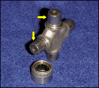
A u-joint that is subjected to a stationary fixed position, especially if at a near 'zero' angle, will risk being damaged due to a condition called 'brinelling'. This results in the needle bearings pounding themselves into the trunion due to prolonged contact in that same area. When an u-joint is on an angle, the twisting motion of the cap slowly rotates the needles bearings to a new location every time it moves.
Without that twisting motion, the needles stay in the same spot and create tiny dents, or grooves in the trunion over time. Then when the u-joint in fact moves (as in a hard acceleration in a rear driveshaft), the brittle needle bearings rumble over these dent-like 'speed-bump', and usually disintegrate, resulting in an immediate u-joint failure. The most common cause of this condition is improperly aligned driveshafts. The straight-on condition will deteriorate the u-joint over time, and usually when in a power required situation, the u-joint will seemingly fail all at once.
Example of "brinelling"

70 F100 LB 2WD, 360FE, E-Street EFI, TKO-500, 76K original miles.. follow my rebuild: The Lo-Buck Bumpside
71 F250 LB, 2WD, 360FE, T18, PS, PB, D60 with 4.11s
73 F100 SB 4WD, 390FE, NP435, +4 on 35s
01 Ferrari 360 Spider F1
01 F150 SuperCrew Lariat 4WD
01 PT Cruiser Limited (DD)
68 Mustang
65 Mustang
71 F250 LB, 2WD, 360FE, T18, PS, PB, D60 with 4.11s
73 F100 SB 4WD, 390FE, NP435, +4 on 35s
01 Ferrari 360 Spider F1
01 F150 SuperCrew Lariat 4WD
01 PT Cruiser Limited (DD)
68 Mustang
65 Mustang